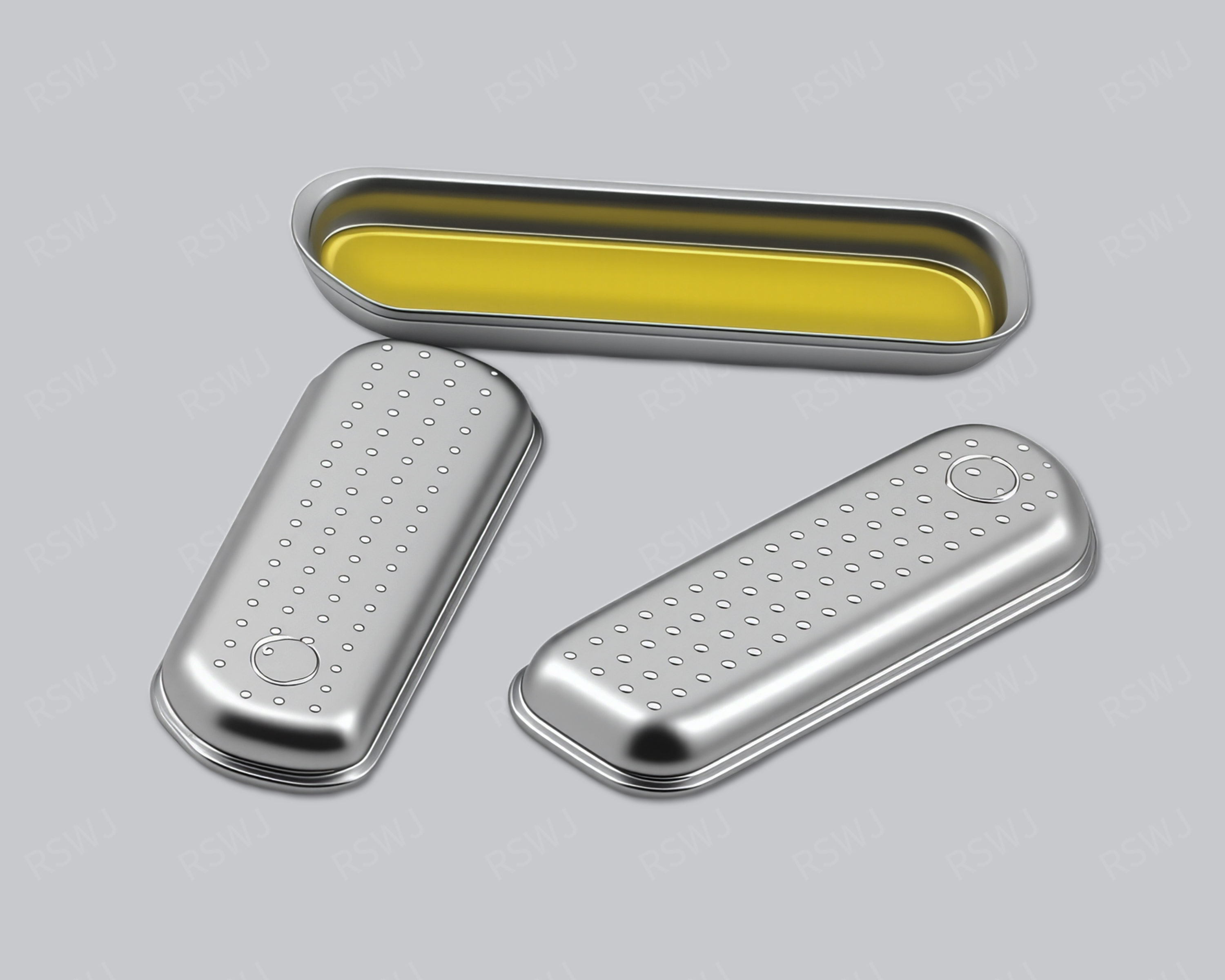
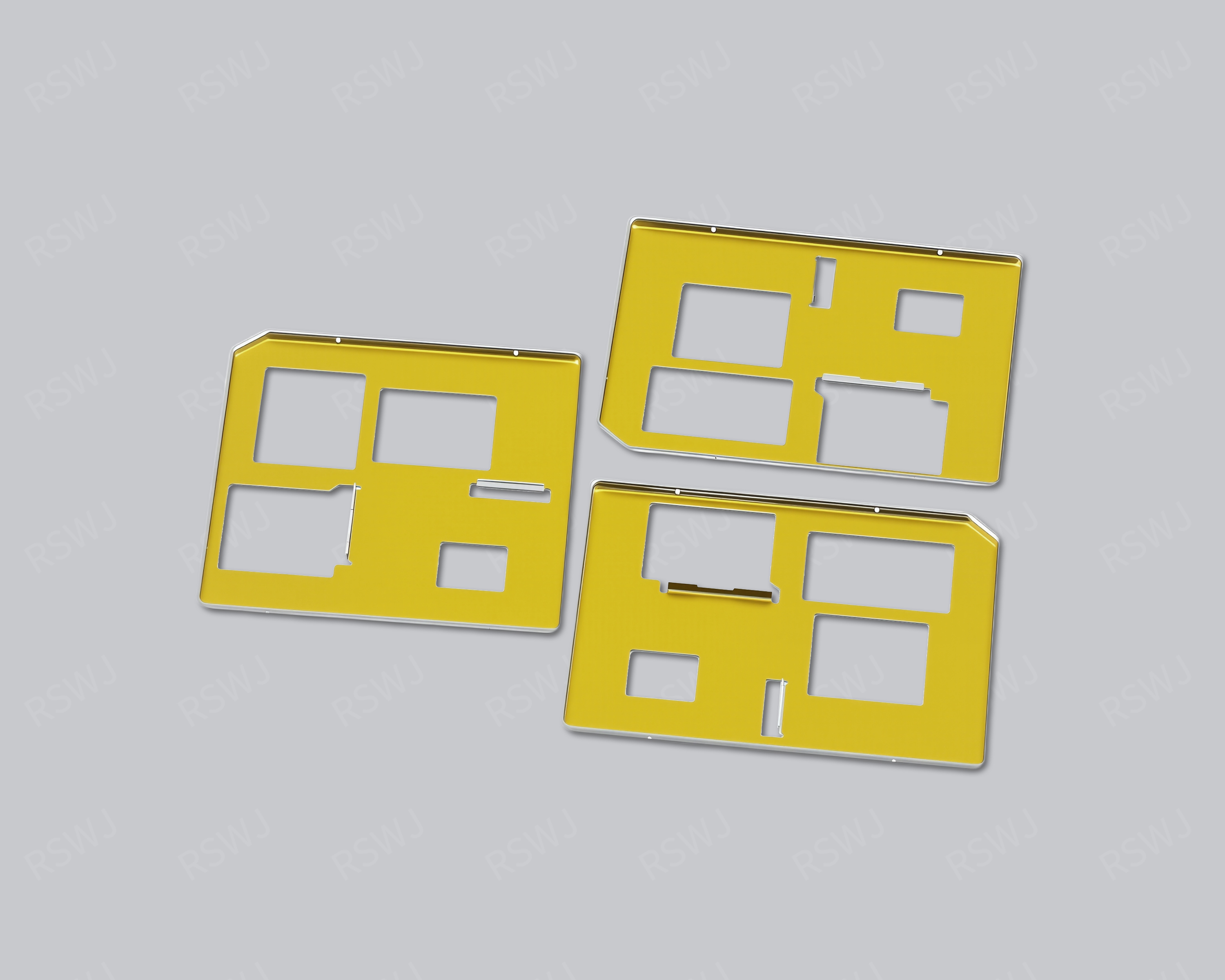
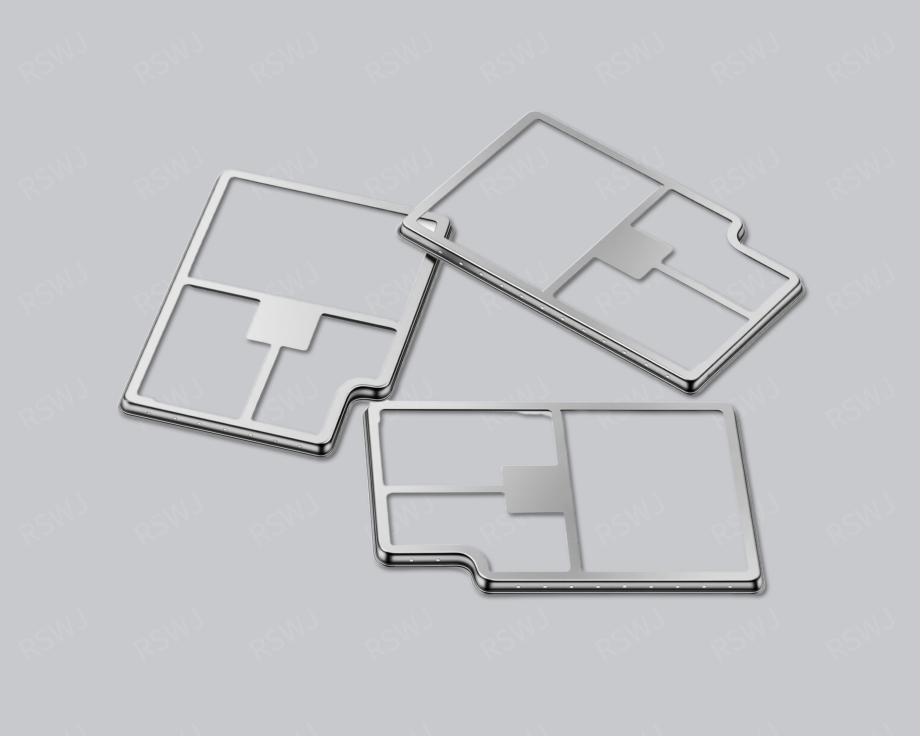
Coverage in one enclosure
Specify the covered area, outline and mounting boundary within the same part revision.

 Enlarge image
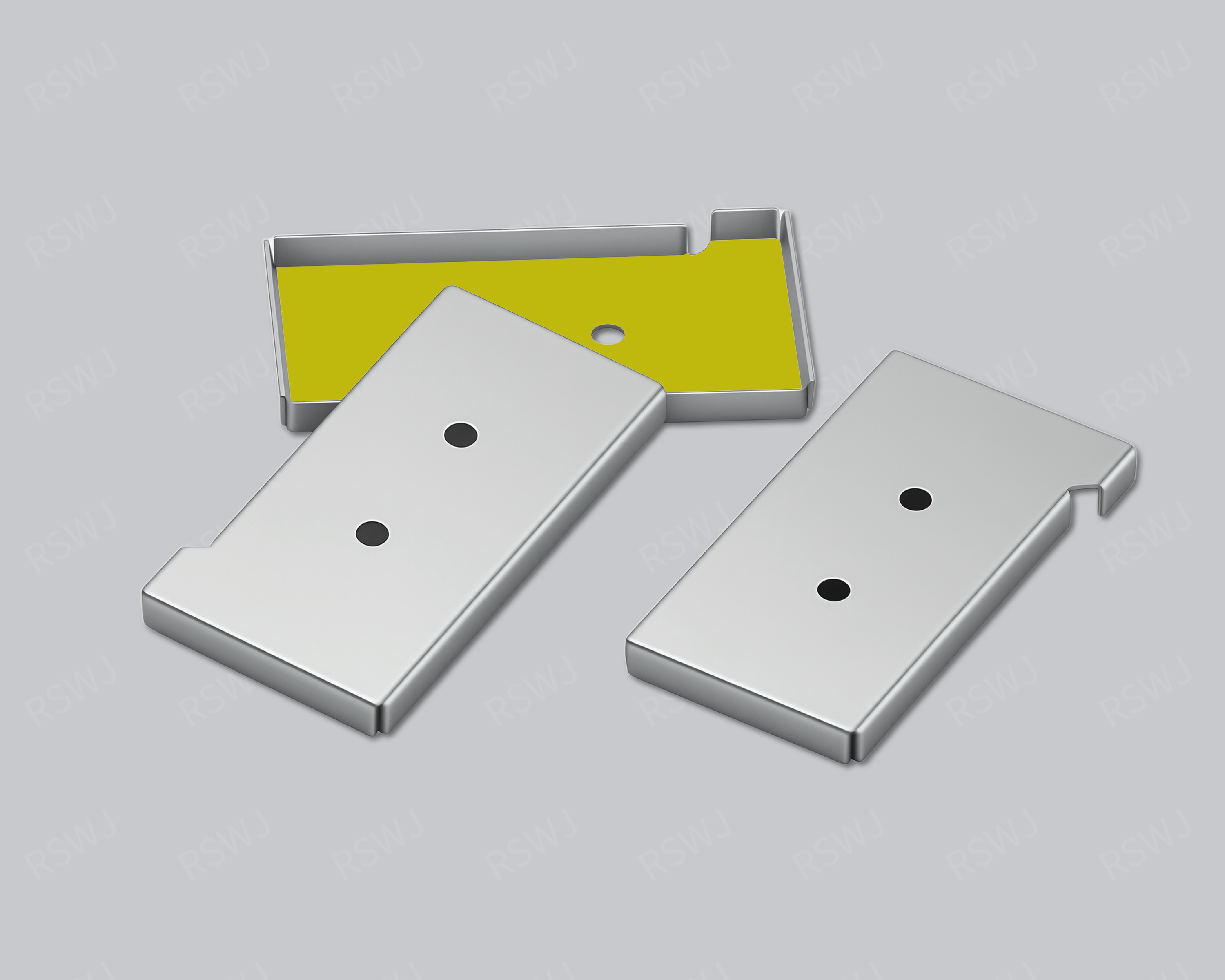
ONE-PIECE SHIELDING CAN
Review the body outline, covered height and installation boundary, then decide whether the assembly needs access after installation.
A single board-level enclosure, customized around component height, mounting boundaries and openings.
Use the image as a design reference. The agreed drawing and sample define the supplied part.
STRUCTURE & FUNCTION
A one-piece shielding can provides coverage with a single enclosure designed around the mounting location on the board. Define the outline, usable internal height and service access together, then select a suitable material and manufacturing route.
Specify the covered area, outline and mounting boundary within the same part revision.
Review connector clearances, locating or handling openings alongside component height and clearance below the shield top.
Assess stamping or deep drawing against the material, enclosure depth, corners and production demand.
CUSTOMIZATION DETAILS
Share dimensions, mating-part information and operating requirements so we can review the manufacturing and inspection approach.
| Design item | What to discuss | Information to provide |
|---|---|---|
| Outline and coverage | Discuss length, width, profile and boundary around the area to be shielded | Part drawing and PCB or assembly boundary, with units and revision |
| Height and internal clearance | Define external height, usable internal height and component clearances separately | Highest components, available device space and an installed cross-section |
| Openings and keep-outs | Review openings for connectors, locating or handling | Hole locations, their purpose and the area that must remain covered |
| Mounting interface | Develop base features around locating, soldering and grounding | PCB land pattern or mating geometry, with the assembly method |
| Material and finish | Agree on material, thickness and treatment through drawings and approved samples | Specified grade, thickness, plating or other surface treatment |
| Sampling and validation | Charged: standard samples 3–5 days; expedited sampling 48 hours; tooling and sample production 7–10 days. Sample stage only; volume production and delivery excluded. Select a suitable process | Dimensional and assembly tasks, sample quantity and project milestones |
DESIGN CONSIDERATIONS
Start with the module location, installation method and access requirements, then resolve the detailed fit.
Read the related design guide ↗Provide the highest component, usable internal height and mounting position when device clearance limits the enclosure. External height alone leaves the internal fit undefined.
Describe debugging and rework tasks, whether the complete can needs to be removed and the space available for that operation.
Show each opening, its purpose and the object it must clear while retaining a defined coverage boundary.
DESIGN CONSIDERATIONS
DRAWINGS & REQUIREMENTS
TOOLING & SAMPLE VALIDATION
Ruishuo makes tooling in-house, connecting die design and CAD/CAM simulation with stamping and inspection. The tooling route for your part is reviewed against the agreed drawing, material and assembly requirements.
A one-piece shield combines its roof and walls in one formed component. Tooling review should cover wall height, bend positions, corner geometry and the mounting features that locate it on the board. These features need to be assessed together, rather than accepting the external length and width alone.
Paid samples include a full dimensional inspection report. Ruishuo's inspection equipment includes 2.5D vision measurement systems, CMMs and profile projectors; measurement methods and any additional functional checks are selected for the project. Incoming, in-process and outgoing inspections support the agreed requirements as the part moves into production.
DRAWING → SAMPLE → PRODUCTION
Samples are paid, with the scope and cost agreed from your drawing and process requirements. Mass-production and delivery schedules are confirmed separately.
Timings depend on the agreed sample plan.
Tooling and sample production exclude mass-production delivery.
Identify the revision, mating parts, material, critical dimensions and sample quantity.
Confirm the manufacturing route, sample cost and schedule.
Review fit, contact and assembly, then complete the validation required by your project.
Approve the drawing revision, inspection criteria and packaging before scheduling the batch.
PRODUCT FAQ
Bring the available drawing and assembly details, even if some dimensions or material choices are still open.
Discuss your project ↗One-piece describes the structure. The manufacturing route depends on depth, corners, material and quantity; stamping or deep drawing can be assessed for the design.
Use the internal space defined in the drawing, accounting for material thickness, component height and mounting position. The external dimension alone does not define usable clearance.
Openings can be reviewed for connectors, locating or handling. When an opening changes, reassess the coverage area, keep-outs and mounting relationships.
RELATED PRODUCTS
Review the continuous body shape, corner geometry and openings. The drawing determines the forming approach rather than the name alone.
View product ↗Review body depth, corner geometry and material condition before agreeing on forming and hole-making requirements.
View product ↗Specify whether thin refers to wall thickness or installed height, then review component clearance and handling requirements.
View product ↗