Frame base
Review the soldering or other attachment interface, locating features and grounding points against the PCB layout.

IN-HOUSE TOOLING & DIES
Ruishuo designs and makes tooling in-house. For a two-piece shield, the tooling review connects the frame and lid to their mating interface, supported by CAD/CAM simulation and sample inspection.
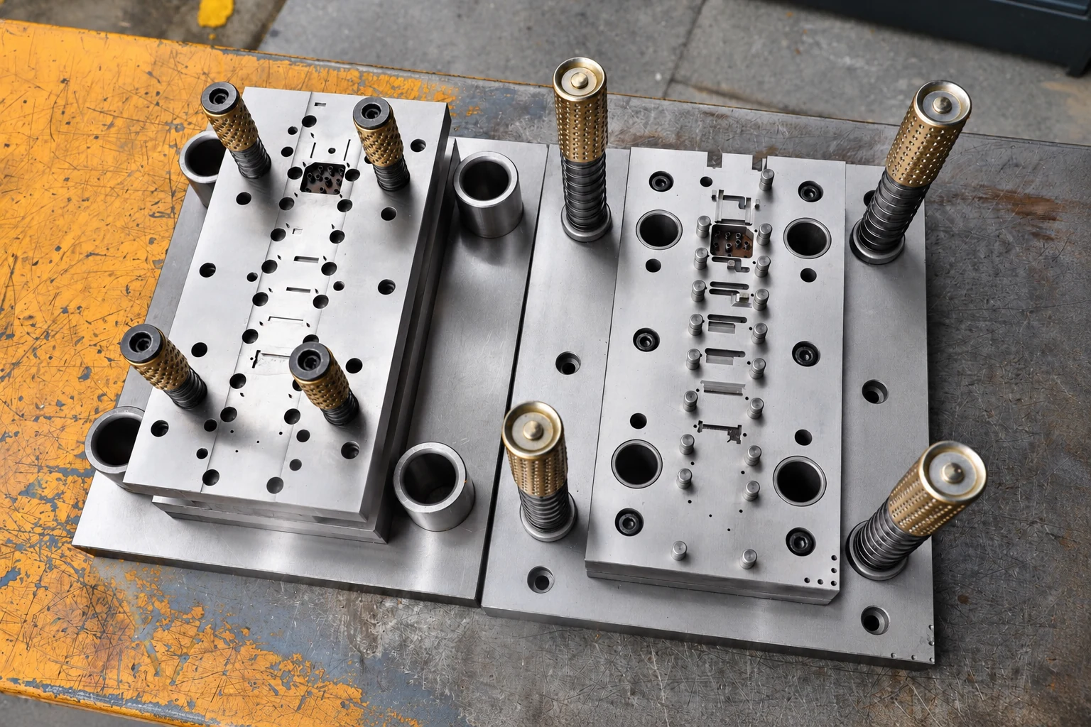
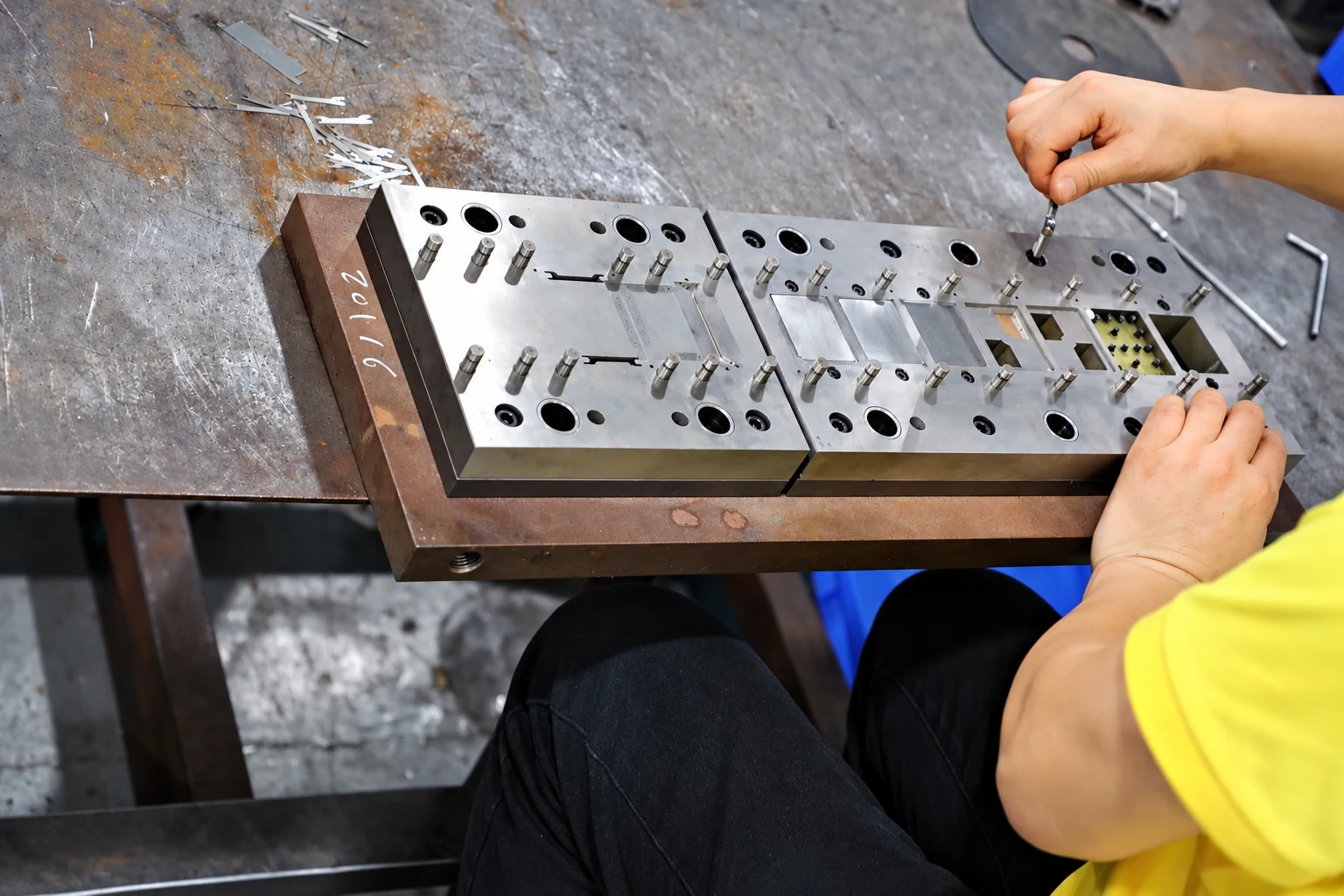
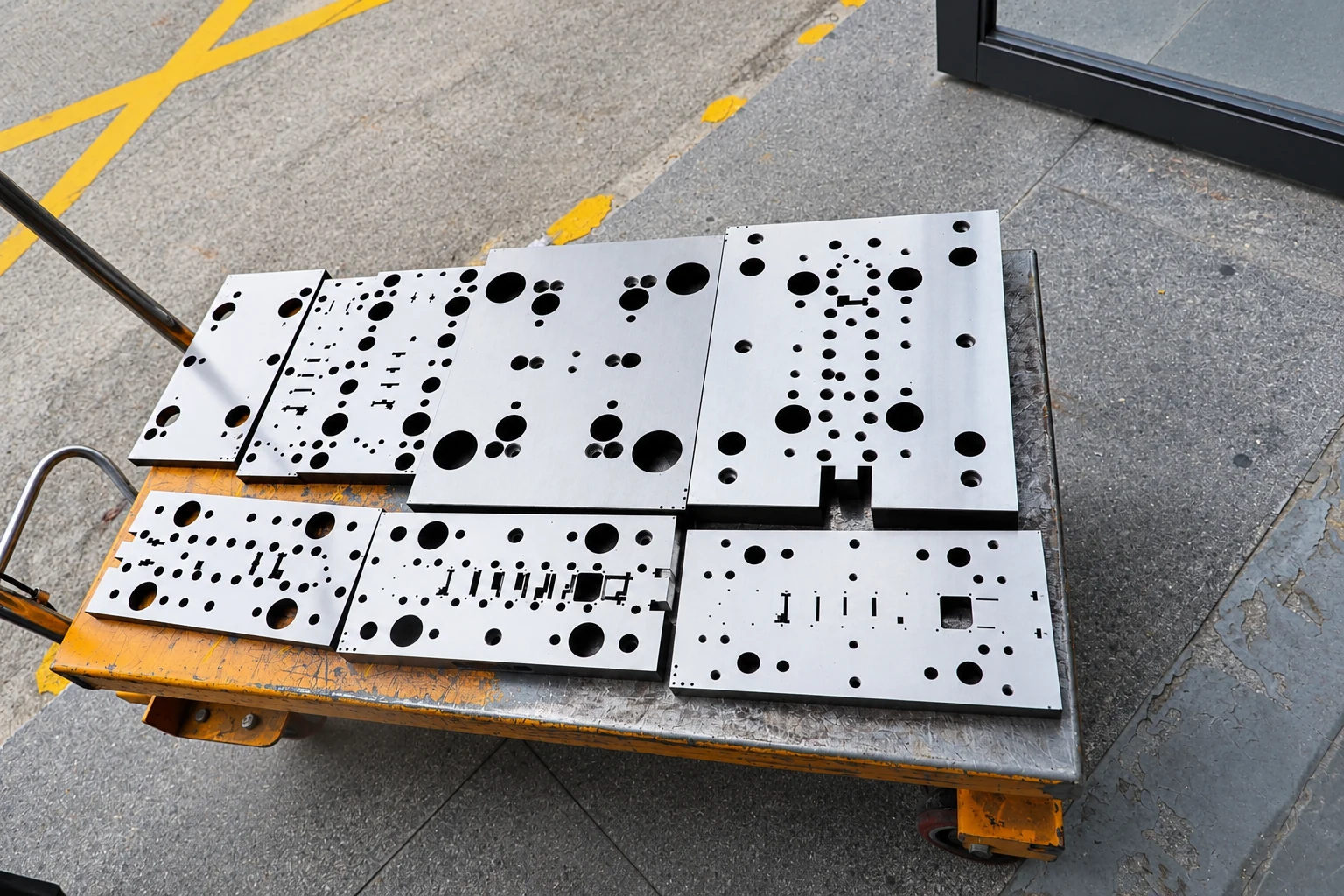
These workshop photographs show factory tooling work. The die design for your project is determined by the agreed drawing.
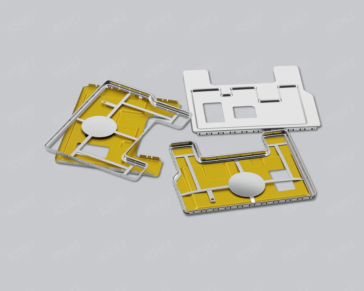
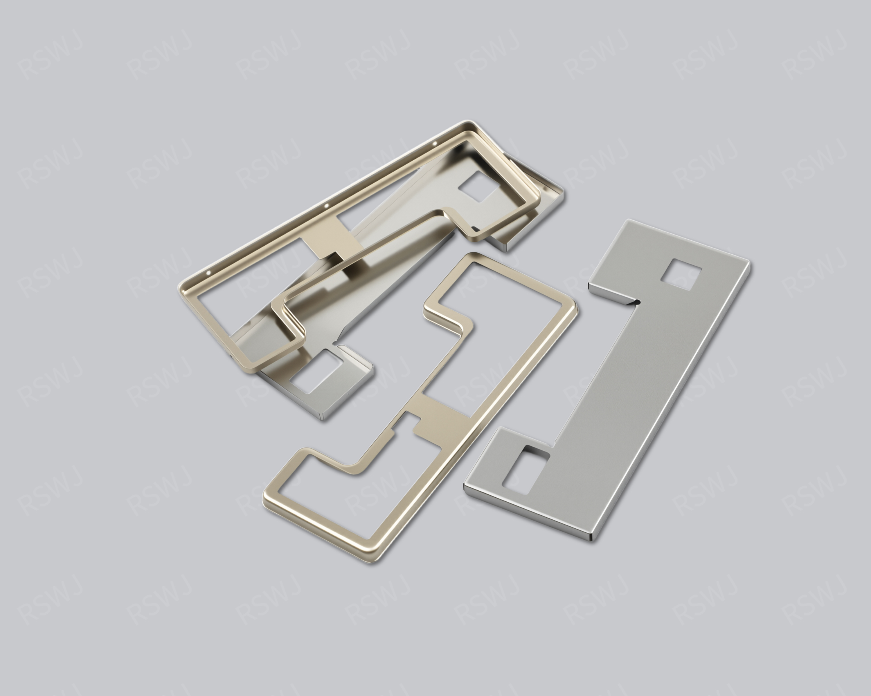
The frame and lid need to work together in the intended assembly. Matching the nominal outline is only one part of the review: seating, overlap and engagement features also affect fit. Bring the mating drawings and service requirements into the tooling discussion before approving each component separately.
Review the sample frame and lid together, as well as their individual dimensions. Paid samples include a full dimensional inspection report; any fit, retention or servicing checks are defined for the intended assembly.
This timing covers the sample stage. Mass-production delivery is agreed separately. Standard samples: 3–5 days; expedited sampling: 48 hours, subject to project feasibility.
A two-piece shielding can consists of a frame and a lid. The frame fits the PCB mounting interface, while the lid can be removed as required by the design. This arrangement supports board-level access for debugging, inspection or rework.
Two-piece, split-type and frame-and-lid are common descriptions of this approach. Compare the actual fit, contact arrangement and removal method rather than treating each name as a different design.
A lid is not a universal replacement independent of its frame. Specify mating dimensions, contact locations and use conditions within the same assembly revision.
Review the soldering or other attachment interface, locating features and grounding points against the PCB layout.
Define clearances, engagement locations and retention requirements together, rather than specifying only two separate outlines.
Select snap-fit or spring-contact features as required by the design, and identify the contact and removal tasks to validate.
Allow for the removal direction, tool access and service frequency so the installed lid can be opened as intended.
Modules that require repeated debugging warrant a close look at the removable lid and spring-contact arrangement. Larger boards and areas containing several modules also need consideration of frame mounting and the space available to handle the lid.
Choose material, thickness and finish for the mating and assembly conditions. Removal, retention and shielding performance should be established through approved samples and validation in the actual system.
| Use case | Main review points |
|---|---|
| Development and debugging | Lid access, measurement space and repeated removal |
| Product rework | Tool clearance, lid handling and protection of the frame |
| Automated assembly | Feeding, locating and handling method |
| Multiple modules | Frame boundary, partitions and grounding design |
For a quotation, provide the frame, lid and assembly drawings together. If a frame already exists, identify its dimensional revision and the intended fit. Drawings and approved samples define the final requirements.
Sample fees apply. Standard samples take 3–5 days, expedited sampling 48 hours, and tooling and sample production 7–10 days. These sample-stage timelines exclude volume production and delivery. Once the sample plan is agreed, confirm matched frame-and-lid quantities, packaging and production inspection requirements.