Coverage
Mark the components, traces and grounding areas to be covered, along with any locations that must remain open.

IN-HOUSE TOOLING & DIES
Ruishuo designs and makes tooling in-house. For a one-piece enclosure, die design, CAD/CAM simulation and sample inspection connect the drawing to the finished roof, walls and mounting features.
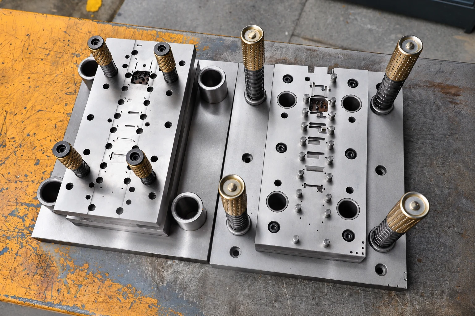
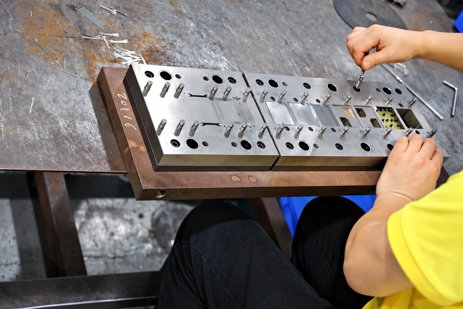
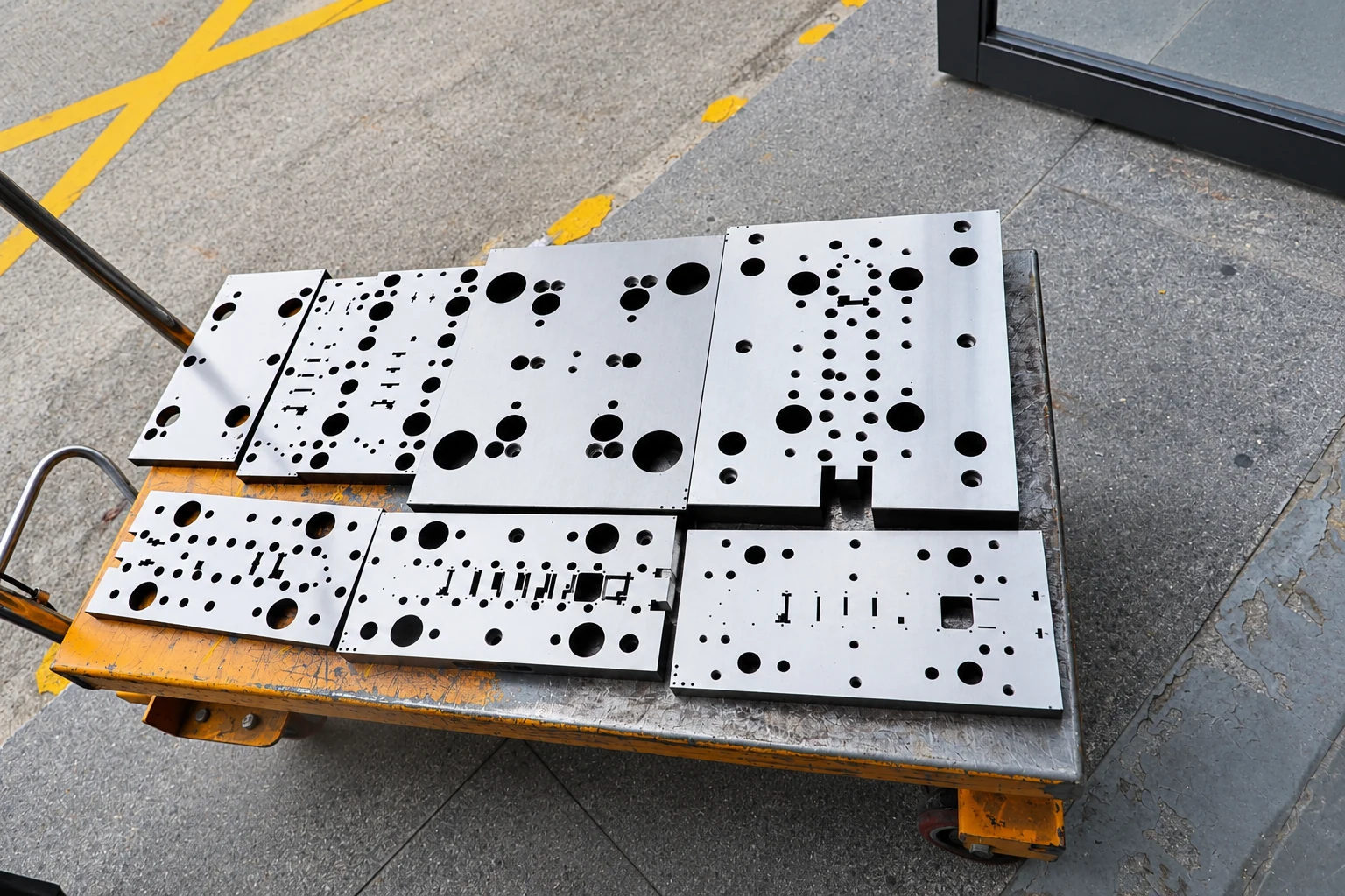
These workshop photographs show factory tooling work. The die design for your project is determined by the agreed drawing.
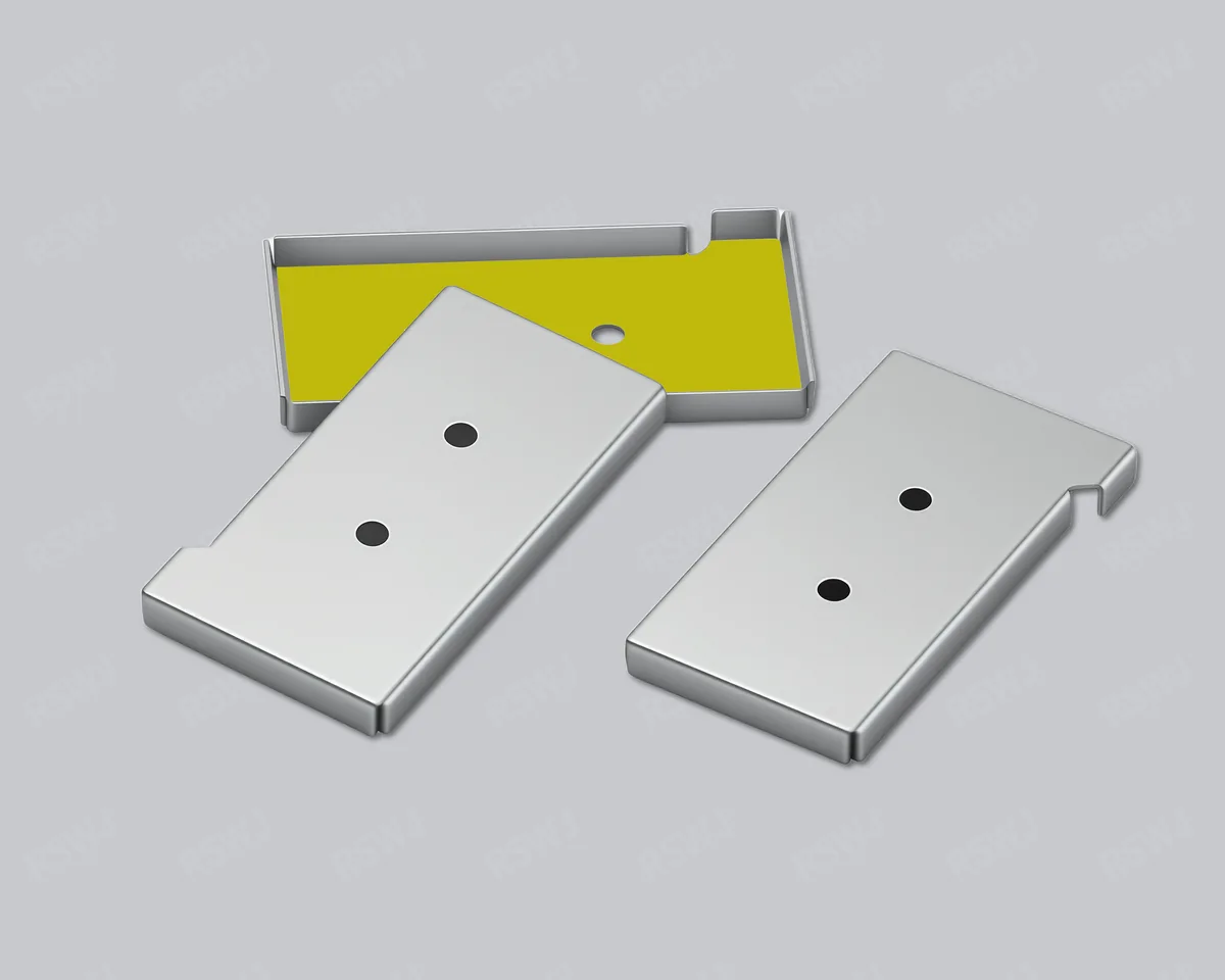
A one-piece shield combines its roof and walls in one component. The tooling review should address the finished geometry, rather than only the flat outline or nominal outside dimensions. Material, thickness and forming details belong in the same discussion as the board interface and component clearance.
Review the formed sample against the agreed drawing revision, with attention to seating, height and component clearance. Paid samples include a full dimensional inspection report; the measurement method and any assembly checks are agreed for the project.
This timing covers the sample stage. Mass-production delivery is agreed separately. Standard samples: 3–5 days; expedited sampling: 48 hours, subject to project feasibility.
A one-piece shielding can uses a single enclosure over a board-level module. It suits designs that do not require frequent access to the enclosed components. Start with the area to be covered, the can height and the mounting boundary, then define the material and manufacturing requirements.
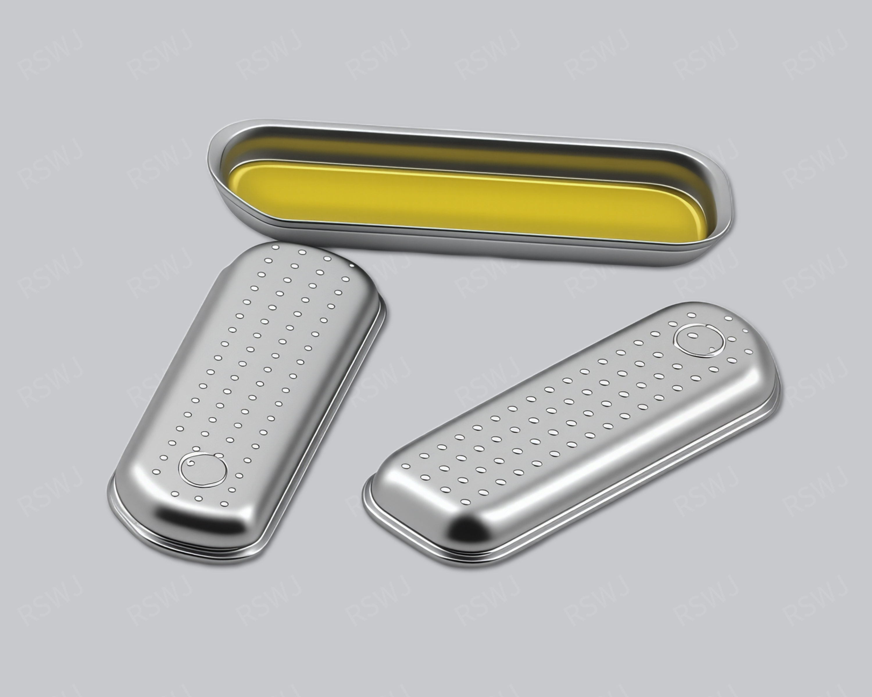
Ruishuo Metal supports custom stamped and deep-drawn designs. Miniature, low-profile and shaped enclosures are assessed against the actual drawings. Dimensions and assembly requirements are established through the drawings and approved samples.
The shield outline has to work with the PCB, component layout and assembly sequence. Length and width alone do not define a complete enclosure.
Mark the components, traces and grounding areas to be covered, along with any locations that must remain open.
Provide the maximum component height, clearance below the shield top and available space in the device. Distinguish the external can height from usable internal height.
Describe soldering, locating and grounding requirements, with the relevant PCB land pattern or mating geometry.
Identify any debugging or rework tasks that require access beneath the shield. Frequent access is a reason to assess a two-piece design as well.
One-piece describes the enclosure structure; stamping and deep drawing describe manufacturing processes. Process selection depends on the material, draw depth, corners, openings and production quantity.
Tinplate, nickel silver and stainless steel are among the material options to discuss. Select the finish around soldering and environmental requirements, then validate shielding performance in the actual mounting and system configuration.
| Input | What to specify |
|---|---|
| Drawing | Outline, can height, wall thickness, corners and hole locations |
| Material and finish | Grade, thickness, plating or other surface treatment |
| Critical dimensions | Dimensions requiring control and the measurement method |
| Assembly | Locating, soldering, grounding and handling method |
Send drawings, expected quantities and application conditions so we can agree on the process and critical dimensions before producing paid samples. Standard samples take 3–5 days; expedited sampling takes 48 hours; tooling and sample production take 7–10 days. These are sample-stage timelines and exclude volume production and delivery. The schedule is confirmed for the selected sample plan.
Sample approval should cover dimensional fit, the assembly process and the agreed validation tasks. Before volume production, align the drawing revision, material, packaging and inspection requirements.