Compartment layout
Identify the modules covered by each cavity, component heights and locations that need to remain open for connections.

IN-HOUSE TOOLING & DIES
Ruishuo designs and makes tooling in-house. A partitioned shield needs its internal layout considered alongside the external perimeter, connecting CAD/CAM simulation, forming and sample inspection.
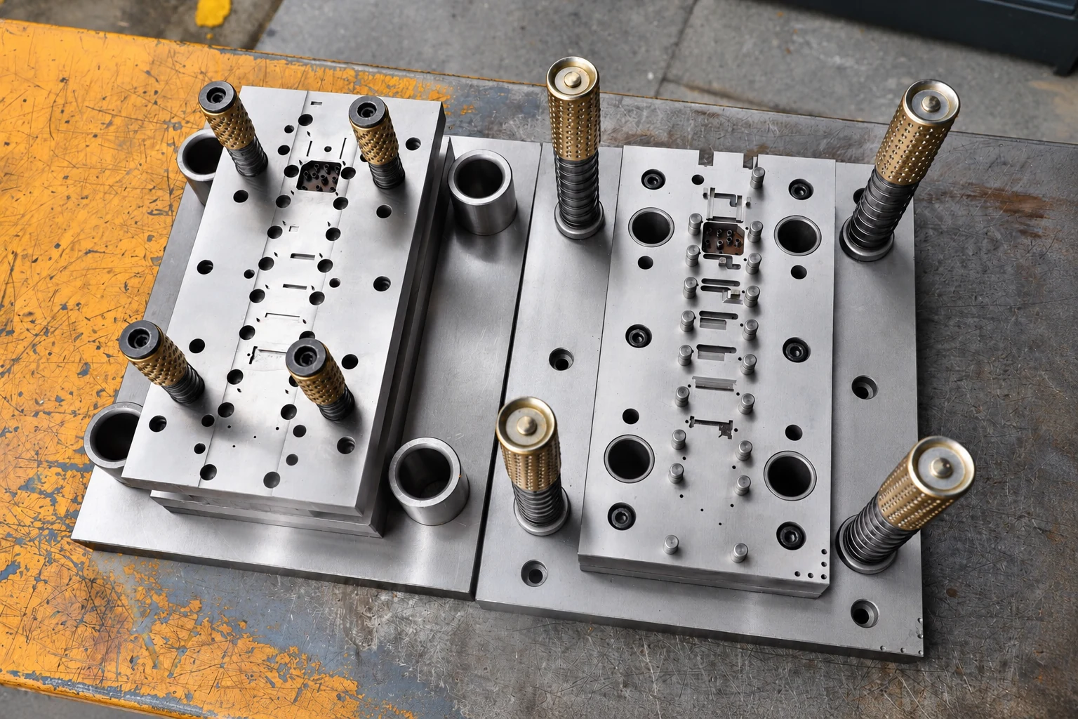
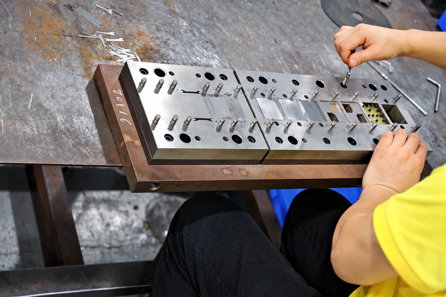
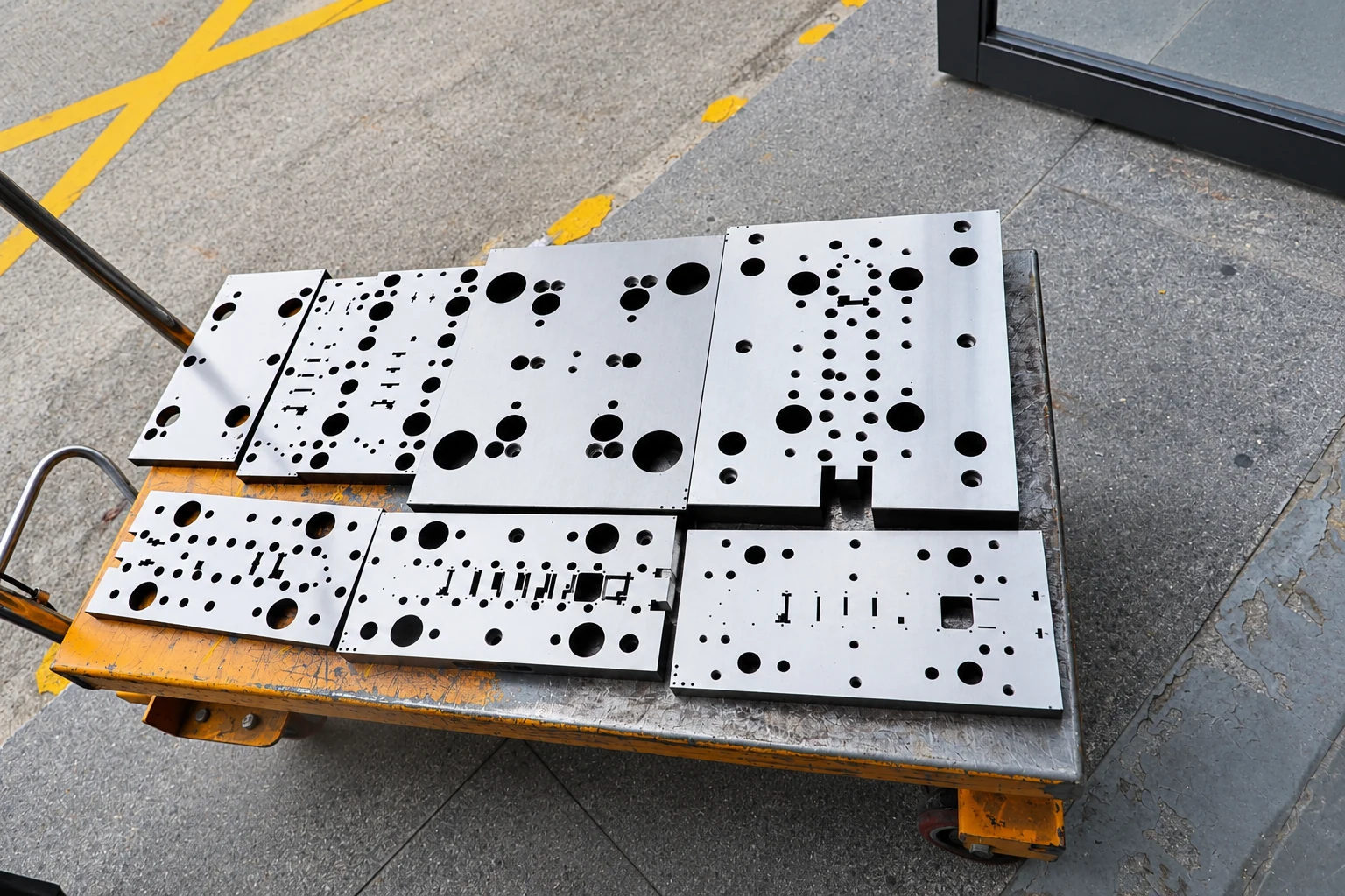
These workshop photographs show factory tooling work. The die design for your project is determined by the agreed drawing.
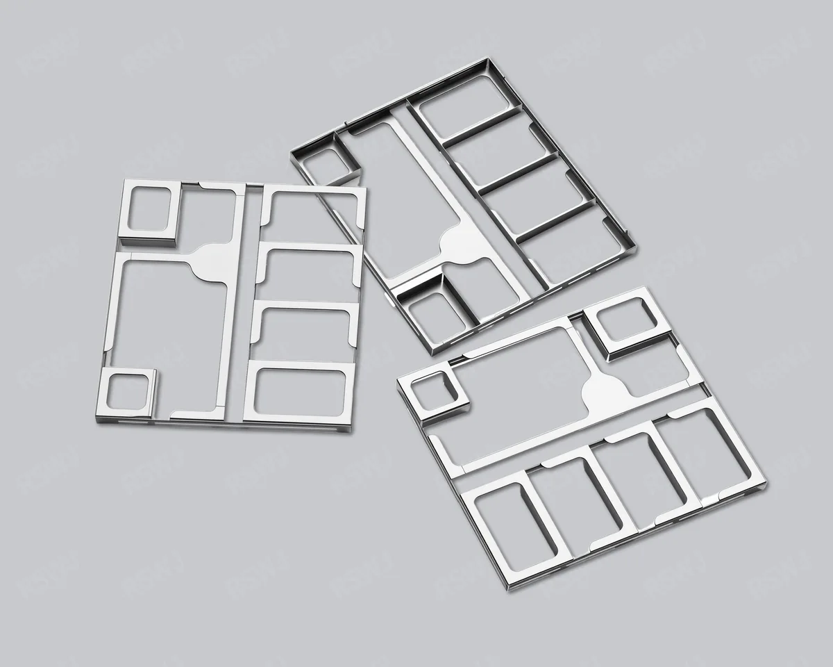
A multi-cavity shield introduces internal walls as well as an outer boundary. An acceptable outer outline does not establish that every partition meets the board layout. Use the PCB context, component heights and agreed datums to define which internal features need control and inspection.
Sample review should cover the perimeter and the internal features that matter to the assembly. Paid samples include a full dimensional inspection report; agree the inspection locations and any mating-board checks before approving the layout.
This timing covers the sample stage. Mass-production delivery is agreed separately. Standard samples: 3–5 days; expedited sampling: 48 hours, subject to project feasibility.
Multi-cavity shielding divides a covered area using internal walls. It is an option for multi-module or multi-band PCBs that require separate compartments. The number of cavities should follow the actual layout and engineering requirements.
Cavity configuration can be combined with a single enclosure, a frame or a removable lid. Define the outer boundary and internal partitions together so their mounting relationships remain consistent.
A useful compartment review shows how the shield relates to the board. A simplified assembly drawing can establish the layout before detailed manufacturing dimensions are completed.
Identify the modules covered by each cavity, component heights and locations that need to remain open for connections.
Show how each partition meets, mounts to or grounds to the PCB, including the space available on the board.
State the purpose of ventilation, locating or pickup holes and check their relationship to the compartment boundaries.
Specify which cavities require access and whether the design calls for full-lid or compartment-level access.
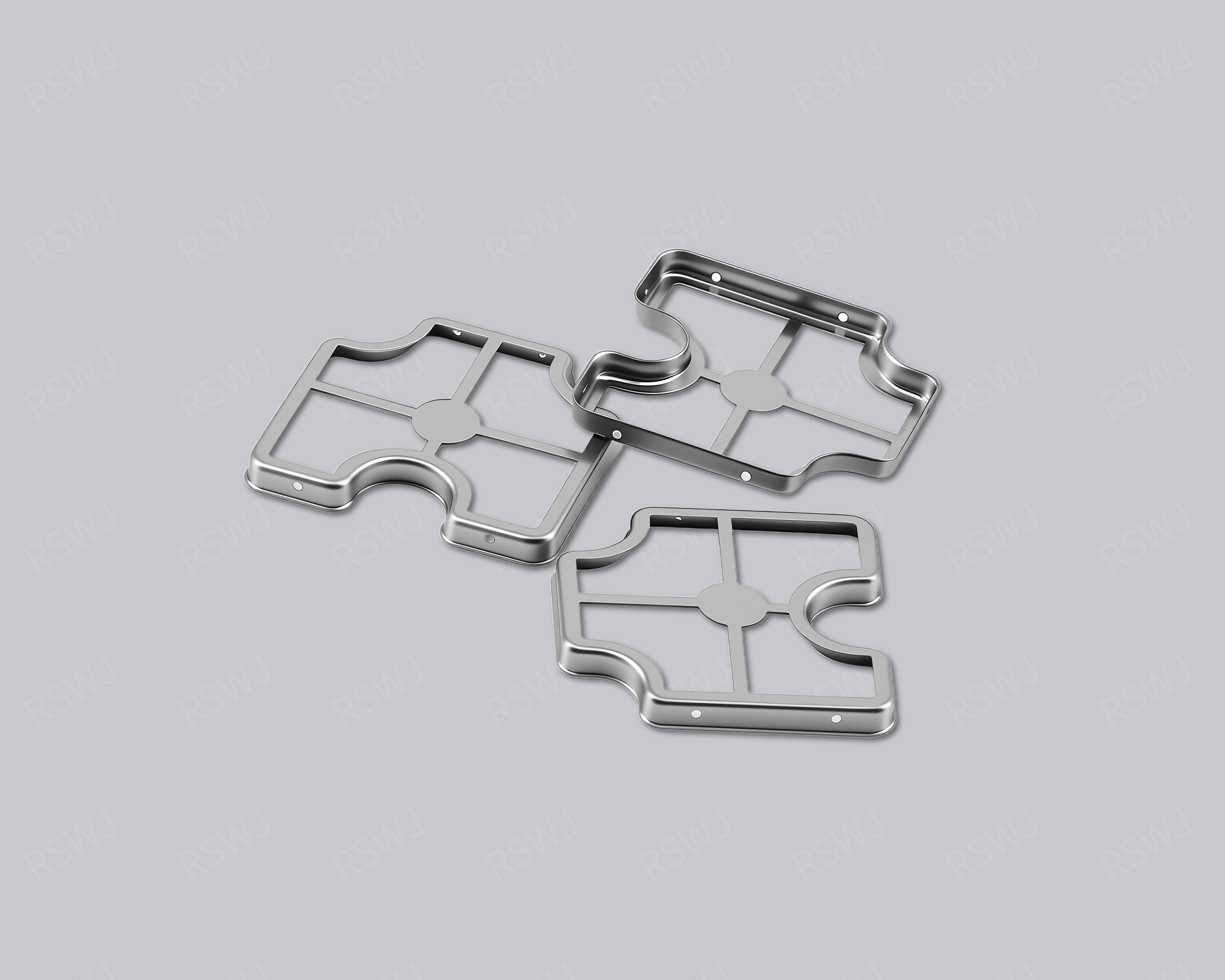
Partitions, the outer frame and critical mating dimensions deserve particular attention in a multi-cavity part. Select material, thickness and finish alongside the forming process and subsequent mounting method.
Ruishuo Metal supports custom review of precision-stamped parts, multi-cavity frames and matching lids. Compartment geometry, dimensional control and inspection methods are established by drawings and approved samples.
| Stage | What to establish |
|---|---|
| Design review | Outer frame, partitions, component clearances and mounting interfaces |
| Sample assembly | Overall fit, locating features and lid handling |
| System validation | Required shielding and functional performance under project conditions |
| Production preparation | Critical dimensions, packaging and inspection tasks |
After sample validation, record the agreed board boundary, partition positions and mating relationships in one drawing revision. Subsequent changes should be assessed for their effect on both the structure and mounting.
Sample fees apply. Standard samples take 3–5 days; expedited sampling takes 48 hours; tooling and sample production take 7–10 days. These sample-stage timelines exclude volume production and delivery. The quotation and sample schedule are confirmed for the specific structure.