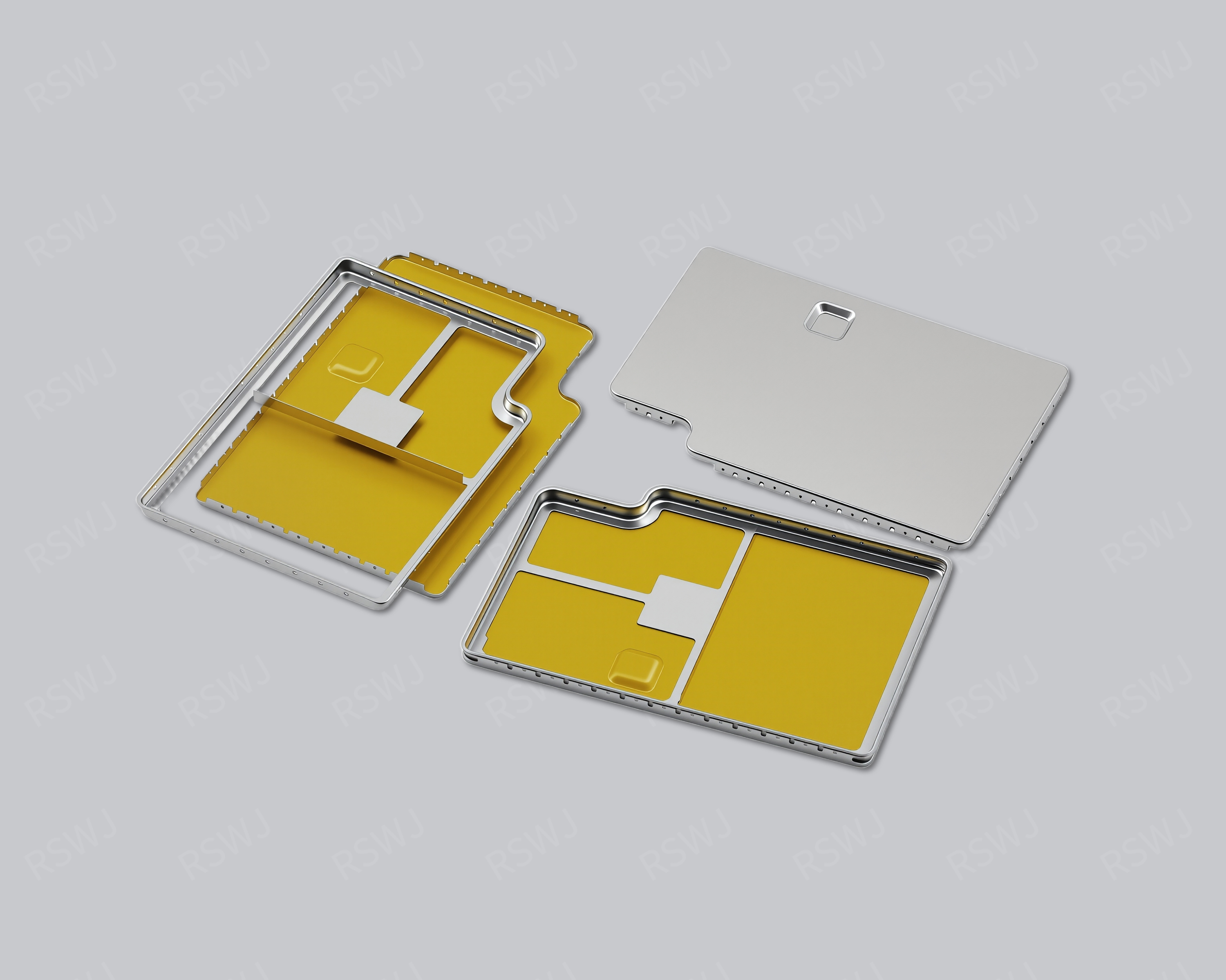
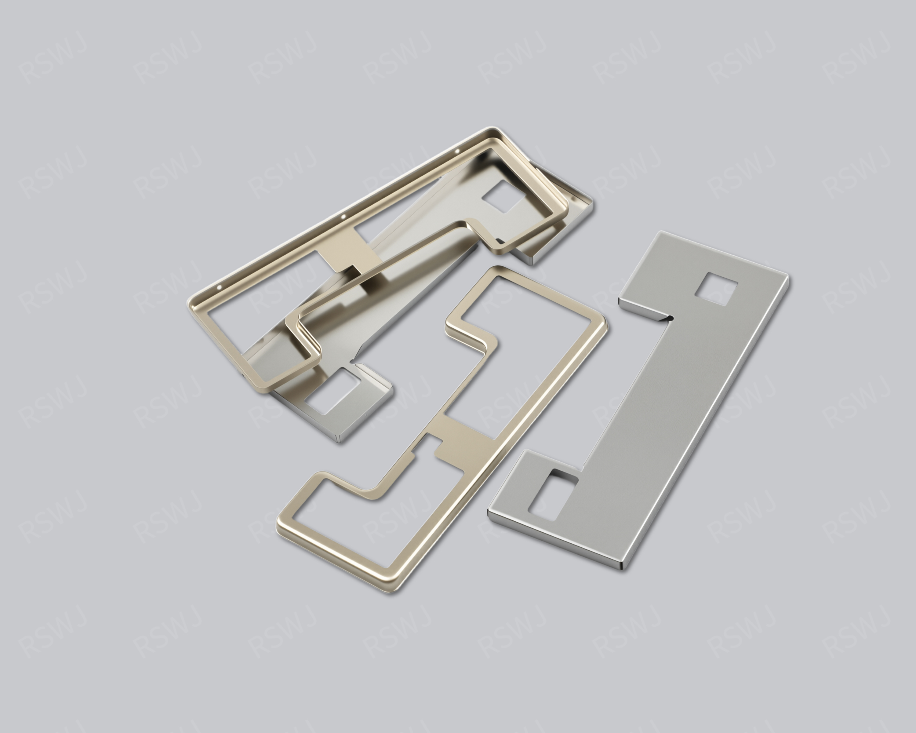
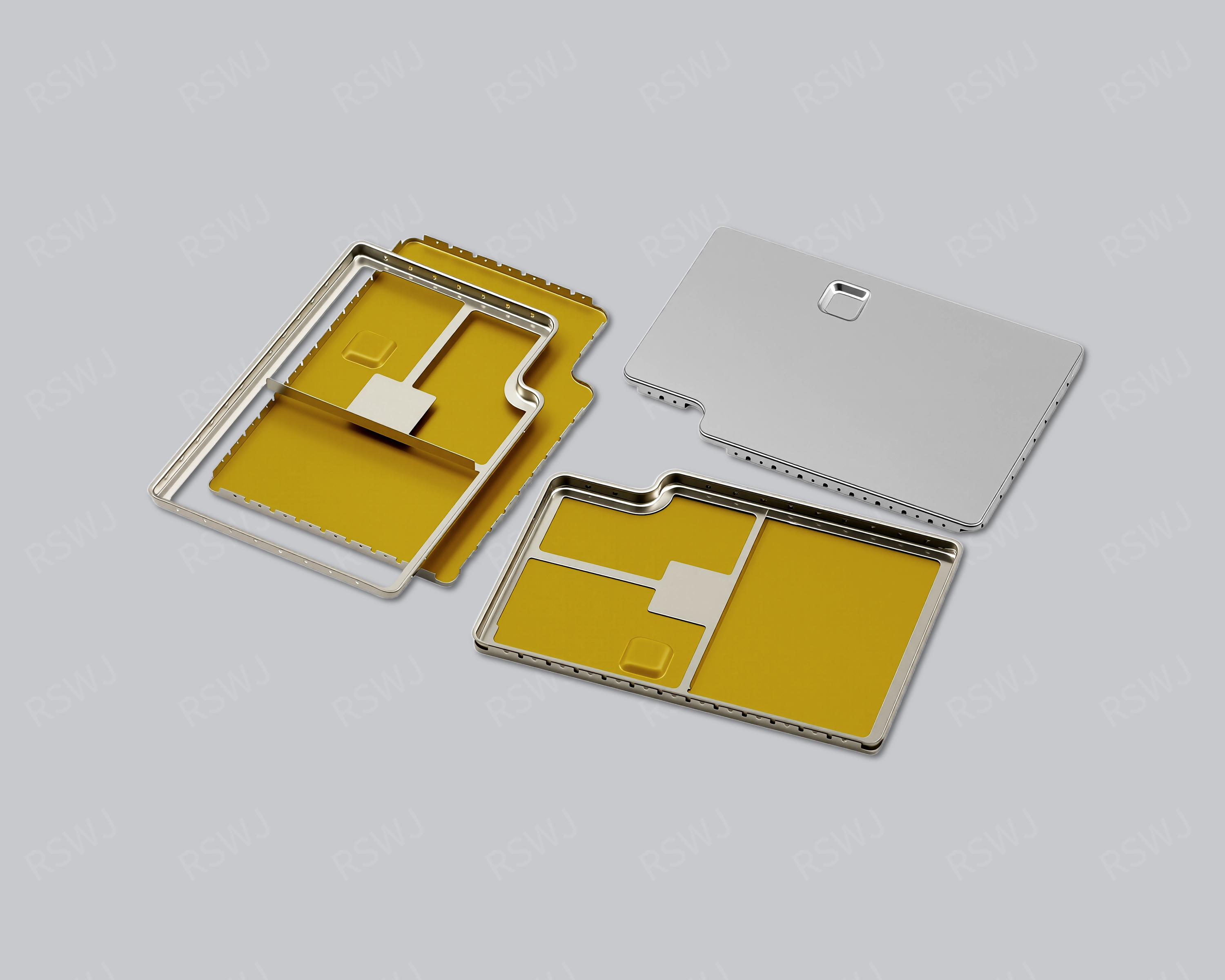
Separate mounting and access functions
The frame fits the board mounting interface; the lid is removed as designed to provide access to enclosed components.

 Enlarge image
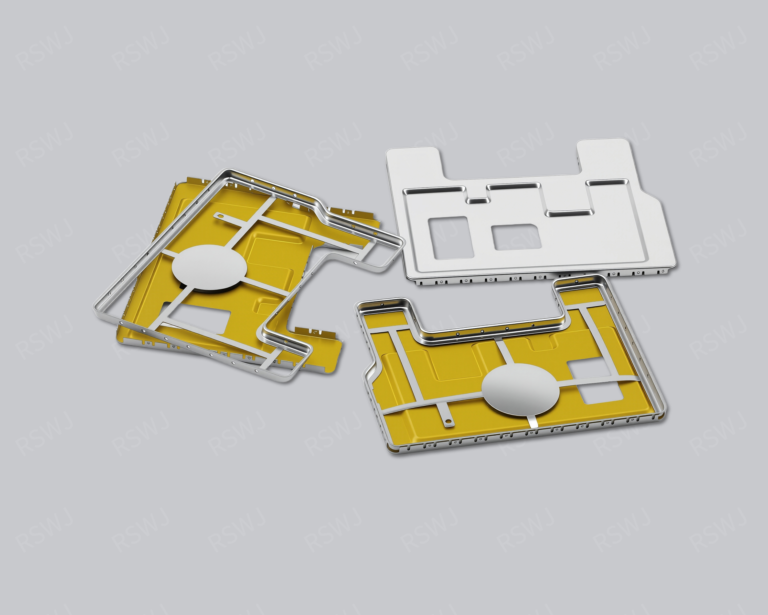
TWO-PIECE SHIELDING CAN
Review frame-to-lid fit, contact areas and the space needed to remove the lid as part of the complete PCB assembly.
A matched frame and removable lid with access for debugging, inspection and rework.
Use the image as a design reference. The agreed drawing and sample define the supplied part.
STRUCTURE & FUNCTION
A two-piece shielding can combines a frame and a lid, with frame mounting and lid removal specified separately. Treat their fit, contact locations and opening clearance as one assembly when selecting the design.
The frame fits the board mounting interface; the lid is removed as designed to provide access to enclosed components.
Choose snap-fit or spring-contact features with clearances, contact locations and retention requirements specified for the assembly.
Specify lid handling direction, tool clearance and service frequency alongside the part geometry.
CUSTOMIZATION DETAILS
Share dimensions, mating-part information and operating requirements so we can review the manufacturing and inspection approach.
| Design item | What to discuss | Information to provide |
|---|---|---|
| Frame and mounting interface | Define the frame around the PCB boundary, locating, soldering or other attachment method | Frame drawing, PCB mating geometry and mounting method |
| Lid and frame fit | Agree on the lid outline, mating clearance and engagement locations together | Frame and lid drawings with a complete assembly revision |
| Contact features | Select snap-fit or spring contacts as designed and define their working areas | Contact locations, mating parts and inspection tasks |
| Opening and service access | Review removal direction and operating clearance for debugging or rework | Tool clearance, removal sequence and service frequency |
| Material and finish | Specify material, thickness and finish for the frame and lid individually | Material and treatment requirements for both parts |
| Assembly samples | Charged: standard samples 3–5 days; expedited sampling 48 hours; tooling and sample production 7–10 days. Sample stage only; volume production and delivery excluded. Confirm a suitable process | Matched quantities, mating assembly and removal or contact tasks to validate |
DESIGN CONSIDERATIONS
Start with the module location, installation method and access requirements, then resolve the detailed fit.
Read the related design guide ↗Define the measurement area, opening direction and tool clearance when enclosed components need probing or adjustment.
If the frame is to remain installed, specify how the lid is lifted, the operating boundary and nearby components requiring protection.
Provide the current frame revision, a sample or drawings, with engagement, contact and retention requirements.
DESIGN CONSIDERATIONS
DRAWINGS & REQUIREMENTS
TOOLING & SAMPLE VALIDATION
Ruishuo makes tooling in-house, connecting die design and CAD/CAM simulation with stamping and inspection. The tooling route for your part is reviewed against the agreed drawing, material and assembly requirements.
For a two-piece or removable shield, the tooling review includes the interface between the frame and lid. A lid that matches the nominal outline may still need adjustment at its engagement points. Sample review should therefore cover the assembled pair, with any removal and retention requirements agreed for the intended use.
Paid samples include a full dimensional inspection report. Ruishuo's inspection equipment includes 2.5D vision measurement systems, CMMs and profile projectors; measurement methods and any additional functional checks are selected for the project. Incoming, in-process and outgoing inspections support the agreed requirements as the part moves into production.
DRAWING → SAMPLE → PRODUCTION
Samples are paid, with the scope and cost agreed from your drawing and process requirements. Mass-production and delivery schedules are confirmed separately.
Timings depend on the agreed sample plan.
Tooling and sample production exclude mass-production delivery.
Identify the revision, mating parts, material, critical dimensions and sample quantity.
Confirm the manufacturing route, sample cost and schedule.
Review fit, contact and assembly, then complete the validation required by your project.
Approve the drawing revision, inspection criteria and packaging before scheduling the batch.
PRODUCT FAQ
Bring the available drawing and assembly details, even if some dimensions or material choices are still open.
Discuss your project ↗Engagement, clearances and contact locations also have to match. Review the new lid against the existing frame in one assembly revision, then validate with matched samples.
A frame-and-lid design can be developed around leaving the frame in place while removing the lid. Confirm the removal method and operating clearance for the mounting arrangement.
Those names may refer to the same frame-and-lid approach. Compare the actual fit, contact structure and removal method to distinguish the designs.
RELATED PRODUCTS
Review the separate shield parts as one assembly, including mating dimensions, assembly order and service access.
View product ↗Confirm which part is removable, how it is retained and how contact is maintained during the required access and reassembly.
View product ↗Define the frame's inner and outer boundaries, then review the mating cover, solder locations and contact points.
View product ↗