Frames & Components
EMI Shielding Fence
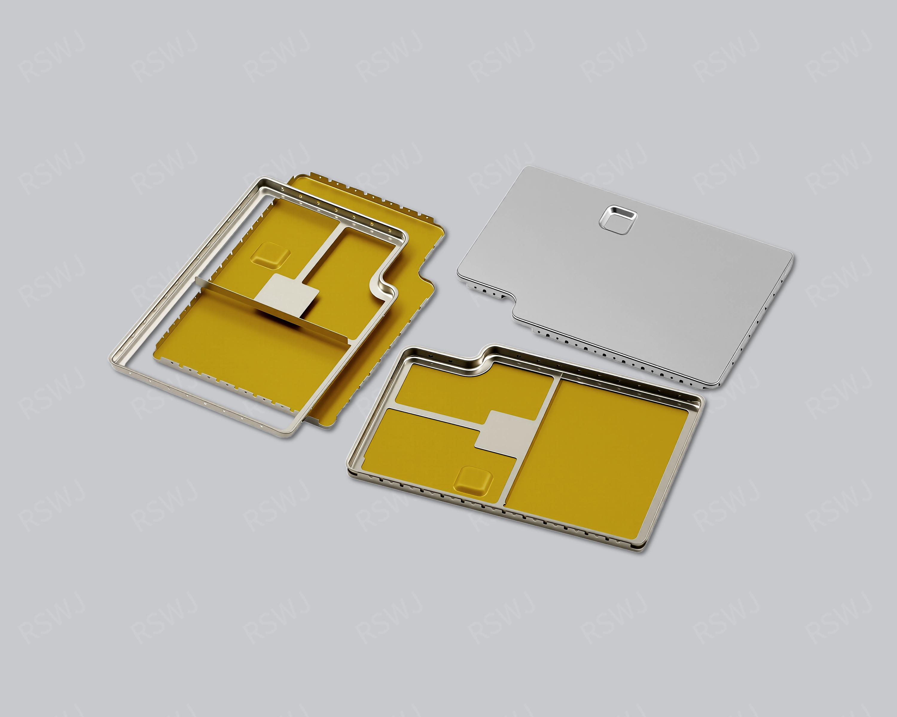
Review the fence's board position, edge dimensions and mating parts together with locating and grounding requirements.
View product
Frames & Components
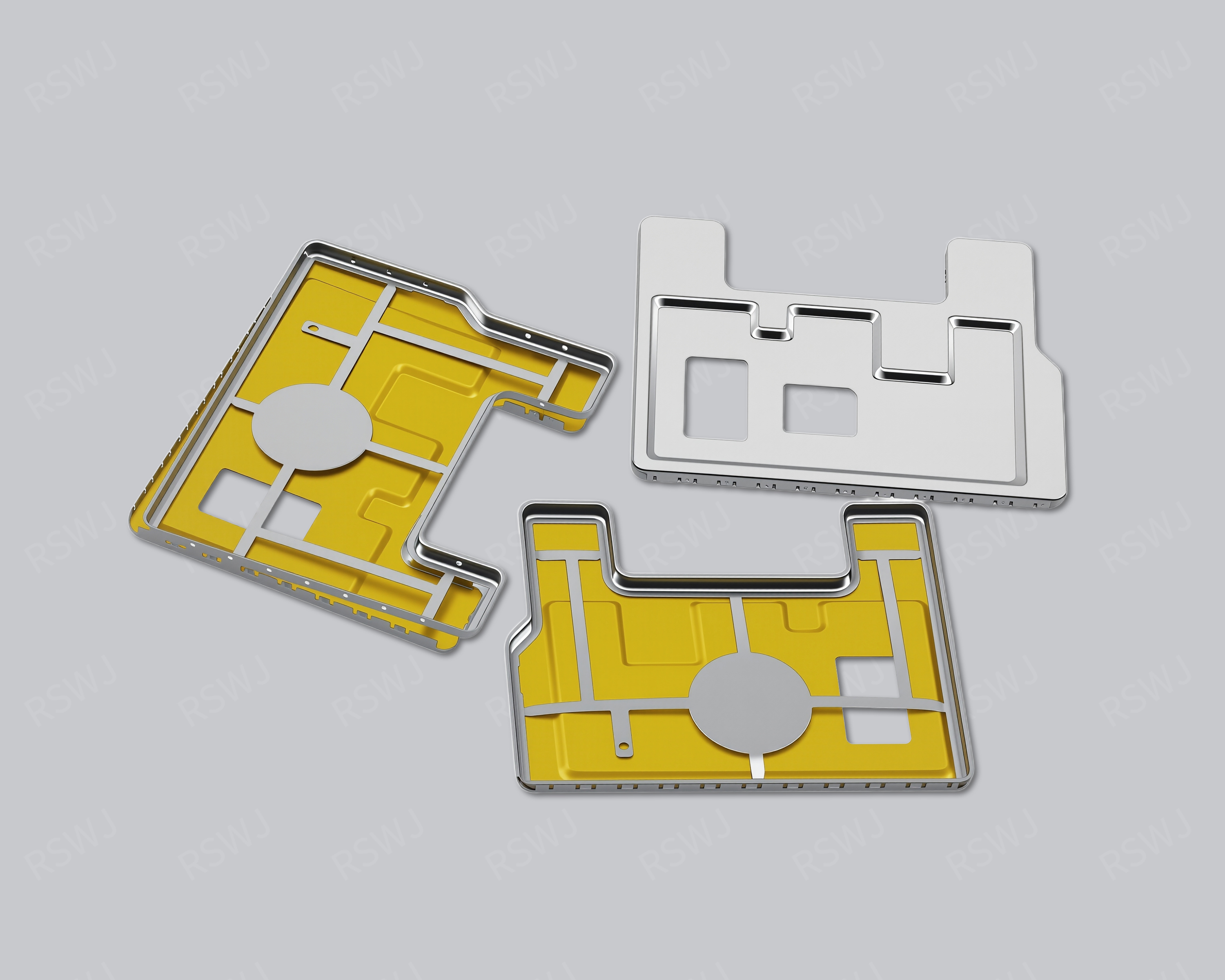
Review the frame's PCB boundary and its mating lid together, including locating features and electrical contact requirements.
Use the image as a design reference. The agreed drawing and sample define the supplied part.
DESIGN CONSIDERATIONS
DRAWINGS & REQUIREMENTS
Agree on the drawing, manufacturing route and sample scope first. Use the sample to check fit, assembly and the tests required by your project, then confirm the production drawing, inspection plan and packaging.
Samples are paid. Standard samples: 3–5 days. Expedited sampling: 48 hours. Tooling and sample production: 7–10 days. These are sample-stage timings and do not include mass-production delivery; availability and the schedule are confirmed for each project.
TOOLING & SAMPLE VALIDATION
Ruishuo makes tooling in-house, connecting die design and CAD/CAM simulation with stamping and inspection. The tooling route for your part is reviewed against the agreed drawing, material and assembly requirements.
The frame or fence establishes the shield boundary on the PCB and may also locate a separate lid. Tooling decisions should consider the board-side seating surfaces, soldering features, wall position and lid interface where applicable. Reference the mating layout when reviewing the sample so that outline measurements are connected to assembly fit.
Paid samples include a full dimensional inspection report. Ruishuo's inspection equipment includes 2.5D vision measurement systems, CMMs and profile projectors; measurement methods and any additional functional checks are selected for the project. Incoming, in-process and outgoing inspections support the agreed requirements as the part moves into production.
Review the fence's board position, edge dimensions and mating parts together with locating and grounding requirements.
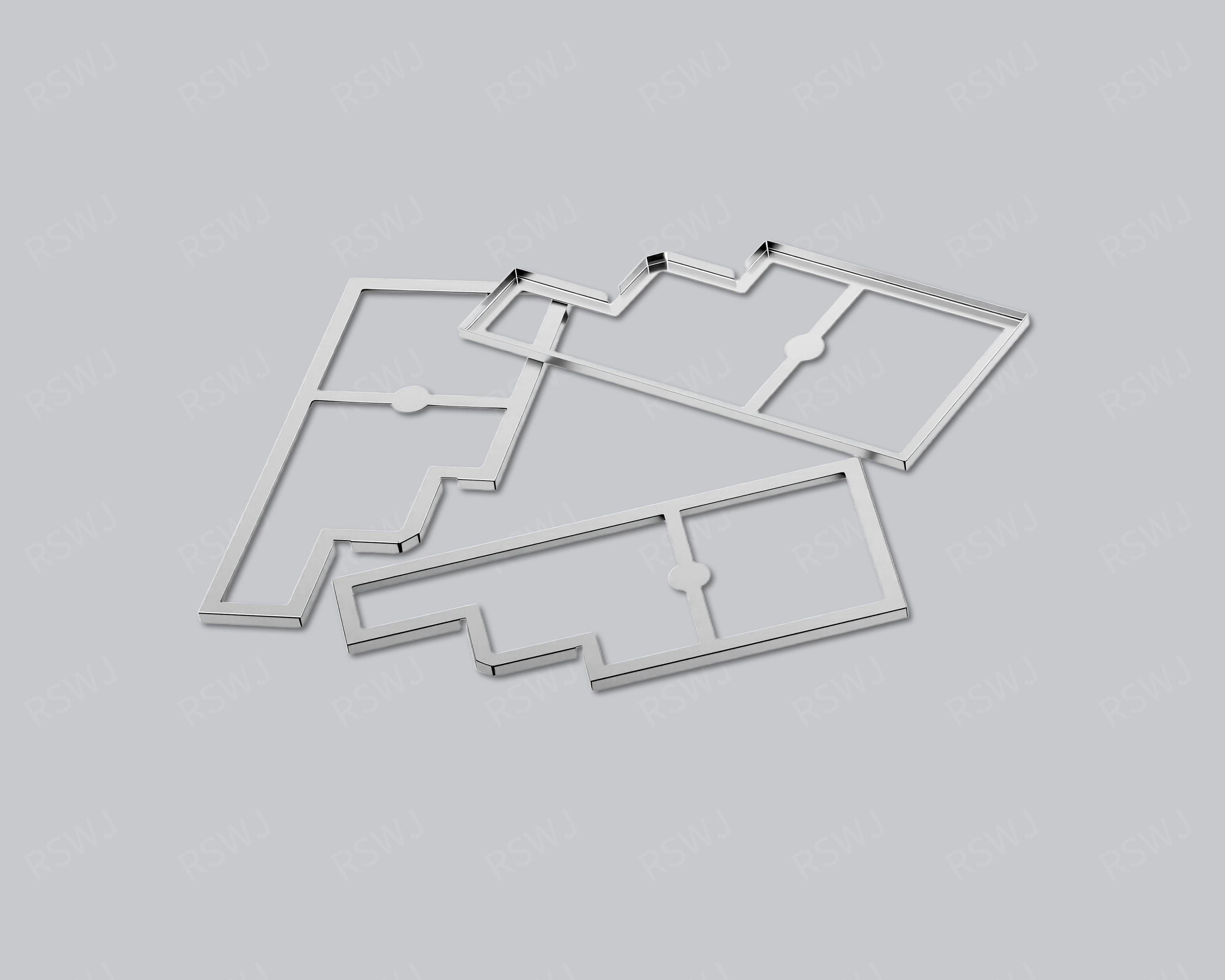
View productDefine the frame's inner and outer boundaries, then review the mating cover, solder locations and contact points.
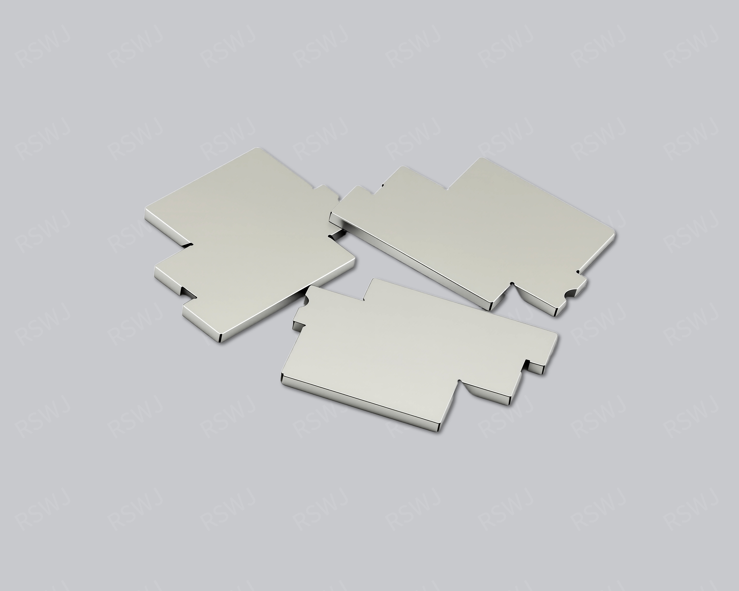
View productMatch the lid to its frame or mounting interface. Review edge fit, removal space and the contact points as one assembly.
View product